I pursued creating ARDMS because of the lack of AM32
firmware availability in the US because of Ukraine and
Russia using autonomous drones in their warfare, but i still
wanted to keep creating and flying my drones. ARDMS is not a
replacement for software like ArduPilot or iNav, it is
simple, reliable, and easy to use firmware that communicates
with Betaflight and its forks. ARDMS is an autonomous racing
drone motion controller firmware built in Python to simplify
drone control. It allows users to program autonomous flight
routes with ease and consistency.
MOSFET
regulation is utilized for the controlling of the ESC,
unlike most F405 firmware versions. The system also includes
automatic
PID loop
calibration for each motor my program acheives this by
strapping the quadcopter to a surface, ARDMS measures the
power curves on each lateral axis to calculate optimal P, I,
and D values for a pre-programmed PID controller based on a
iFlight Nazgul DC5 with stock motors and a 389g payload.
Features
Program custom flight routes with installed GPS module
for predictable autonomous missions
Automatic PID calibration using strapped testing for
initial setup and tuning
Communicates with Betaflight software and its forks for
testing and configuration
Supports ESC communication using MOSFET regulation for
motor control
Utilizes GPS module to plan routes using simple
line-based path following algorithms
Full-duplex serial communication for high-bandwidth data
transfer with MOSFET support
Pics & Demo
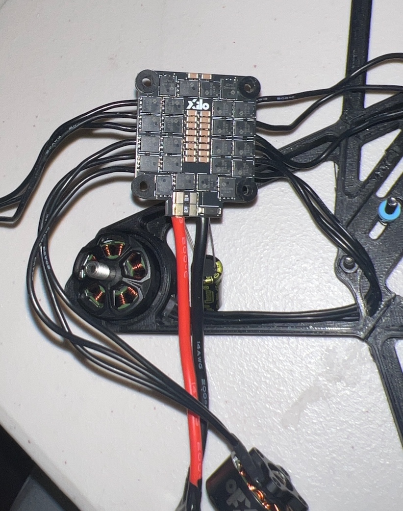
MOSFET layout for ARDMS testing and ESC
communication
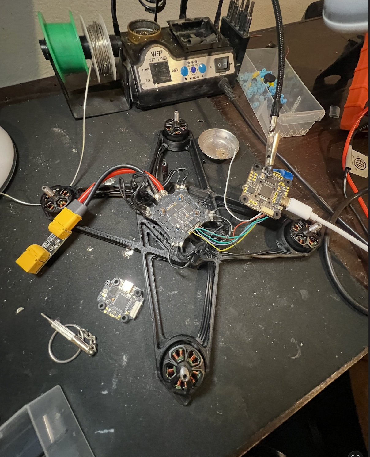
Connection of flight controller with custom firmware
to ESC – testing MOSFET activation
Demo of custom firmware communicating with
Betaflight software. ESC is disconnected to prevent
accidental MOSFET activation.
Development Process
Compared ArduPilot with iNav to determine feature list
Used shoelace theory to determine the area selected by
the user for autonomous flight planning
Implemented automatic PID calibration by calculating
optimal P, I, and D values from measured power curves
Built integration with Betaflight software for testing,
debugging and visualizing motor outputs safely without
arming ESCs
Tested MOSFET activation and motor responses and
refining utilizing the predicted power curves for
accuracy and stability
Added functionality to allow users to program autonomous
routes using a simple, repeatable workflow
Technical Details
Chose MOSFET regulation because AM32 ESCs require MOSFET
regulation to efficiently control motor output. I added
MOSFET regulation because standard F405 stack firmware
distributed in the United States did not support it.
Communication protocol uses DShot because it provided
the highest speed between the stack and ESC while
supporting MOSFET regulation
Used full-duplex instead of half-duplex serial
connection because full-duplex provided the bandwidth
needed for MOSFET regulation over DShot protocol
Installation is performed via the Betaflight firmware
flasher using the firmware provided in the GitHub
repository
PID calibration process involves strapping the drone and
running automated test sequences on each axis to measure
response curves
GPS waypoint system uses
linear interpolation
between points with configurable turning radius for
smooth path following
SWIFT is an open source project developed with two of my robotics buddies
for WSSEF (Washington State Science and Engineering Fair),
where it placed
first in the Engineering category. It
provides a low-cost (<$200/drone) multi-drone search and
rescue platform using a leader-follower coordination
architecture, enabling coordinated search patterns with
efficient area coverage, fast completion times, and low
battery consumption with performance comparable to high cost
commercial drone systems.
The system uses a leader-follower model which is when
one drone computes the global path while follower drones
maintain relative formation positions, calculating movements on one system helps with reducing skew in the model. Artificial
Potential Fields (APFs') is obstacle avoidance and
drone separation, producing smooth, collision free
paths validated through hardware testing. Formation is
managed with multiple route models with aid of LIDAR and visual
data for awareeness of its surrondings.
Search Algorithms
Four search patterns were implemented and evaluated against
area coverage, completion time, estimated energy
consumption, and redundant coverage:
Expanding Square ~80% coverage with
fast completion time, best balance of speed and thoroughness.
Top-performing algorithm in simulations.
Random Walk had faster completion but
uneven coverage. basically it highlights speed over consistency.
Lawnmower had high coverage but slower
due to systematic back and forth sweeping.
Spiral was effective for irregular or
non uniform search areas. terrible at all other perfomance indicators.
The efficiency metric combined coverage, time, and energy
use.
Expanding Square achieved the best results,
reaching ~80% coverage with relatively fast completion time,
balancing speed and thoroughness.
Technical Details
Leader-follower coordination with APF for collision free
drone navigation
At 150ft heat-seeking IR sensors has search resolution of 20x30m for air-to-ground heat
signature detection
Designed to operate under 249g to stay below FAA Part
107 commercial regulations so no authorization required
for deployment
Follower Node: ~$80 (sensors + communication
modules) - STILL WORKING ON FINALIZATION
Leader Node: ~$200 (redundant communication modules +
direct ground connection)
Ground Node: ~$200 (powerful communication unit +
direct connection to leader node)
Search area boundary calculation using the Shoelace
formula for complete path coverage
Programmed in Python
Hardware Prototypes
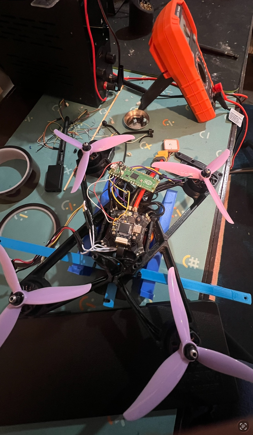
Full leader node prototype, custom quad with
Raspberry Pi Pico flight controller, flight stack,
GPS, and communication module. Pink propellers for
visual identification during swarm testing.
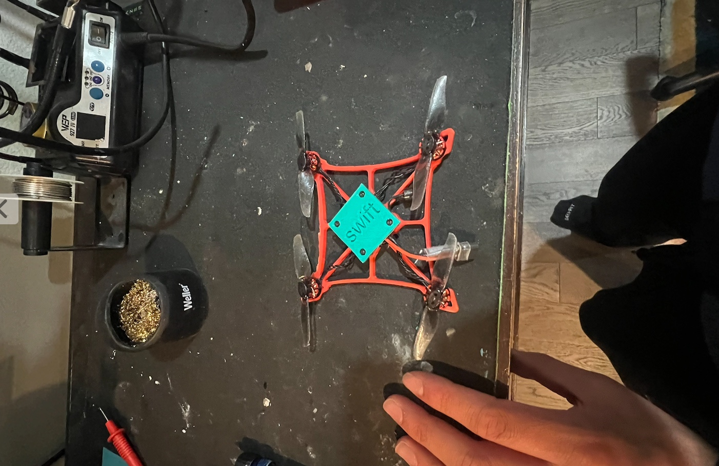
A smaller form factor quad designed to reach into
tight or confined spaces that leader nodes cannot
access. Red coloured 3D-printed frame keeps weight minimal.
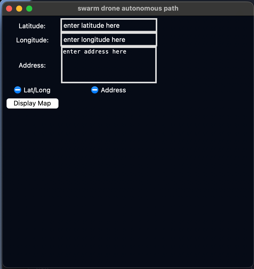
Desktop application for mission planning and swarm
coordination — operators define search areas, assign
search patterns, and monitor individual node health.
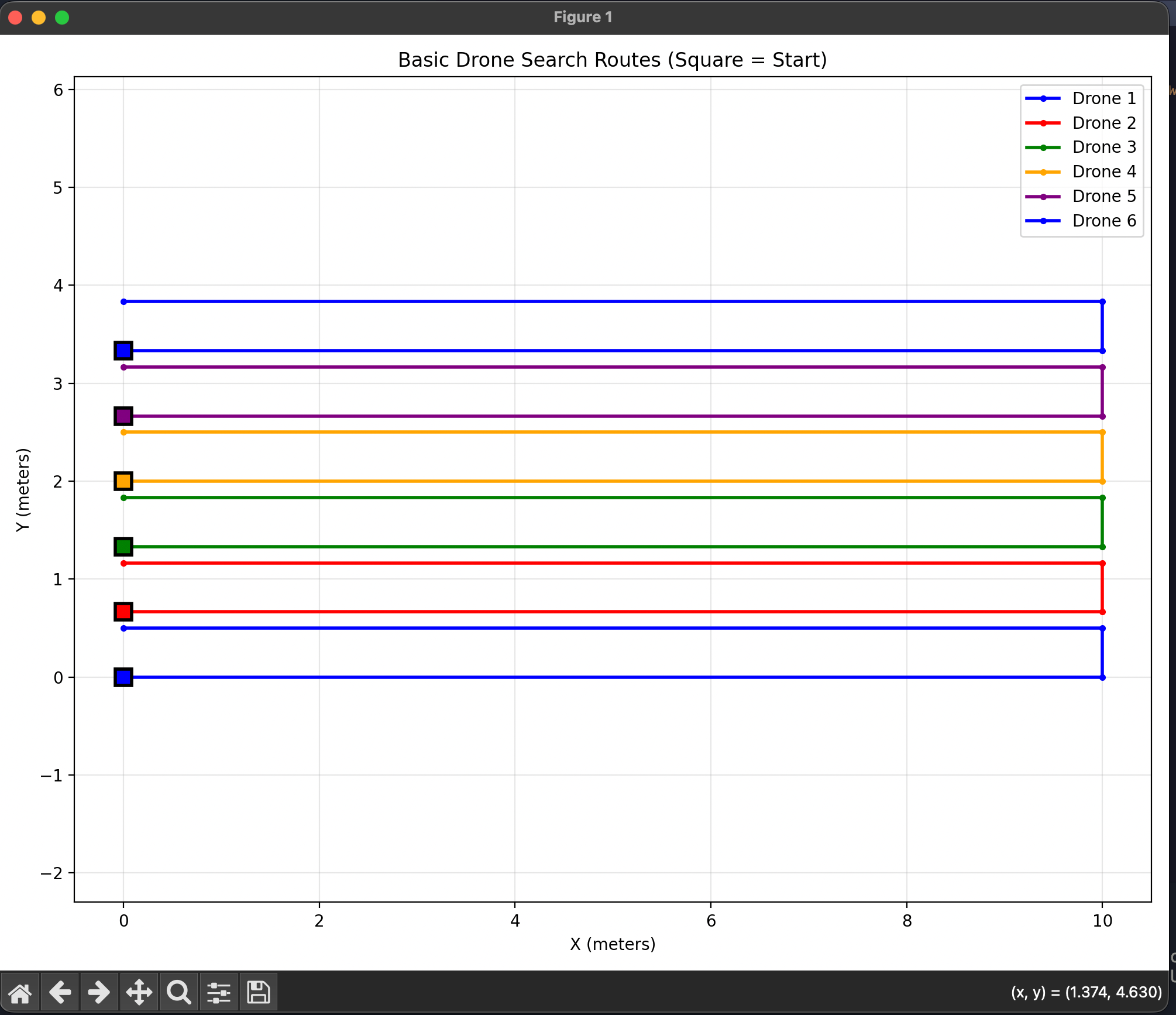
Shoelace-formula area coverage visualization —
ensures the swarm doesn't miss a spot during search.
Kind of like a Roomba, but for disaster recovery.
Results
APF + leader-follower control enabled efficient,
collision-free navigation and reduced redundant movement
Expanding Square achieved ~80% area coverage in
simulations with low time and energy cost
System validated through hardware testing on a low-cost
quadcopter prototype with 3D-printed frame and
lithium-polymer battery
Simulation ran to 80% area coverage OR until battery
dropped to the RTH threshold
Limitations & Future Work
Sensor accuracy — IR detects heat but
can't distinguish vehicles from people; future work will
integrate ML with LIDAR + computer vision for better
target classification
Wireless dependence — leader-follower
relies on stable comms; future versions will explore
decentralized swarm intelligence so each node can act on
local observations alone
Scale validation — tested with a single
follower drone using manual inputs; a full multi-drone
hardware test is needed to fully evaluate APF and
formation coordination at scale
Adaptive hybrid search — a dynamic
algorithm that switches patterns based on real-time
coverage density (e.g., lawnmower + random walk) to
reduce redundancy in partially explored areas
ML target recognition — integrate
computer vision + LIDAR fusion to classify detected
objects and distinguish people from environmental noise
High-Speed 3D Printer with Distributed Computing
Cluster• Computational Offload • 3D Printing
I created this high-speed 3D printer out of curiosity to see
how far I could push an Ender 3 clone (Voxelab Aquila). The
goal was to create a system that would work with the
existing printer hardware while adding extra computational
power. The printer's internal MCU handles motor control and
reads limit switches, while computationally heavy tasks like
path planning, acceleration calculations, and G-code
preprocessing are offloaded to a Minnowboard or Raspberry Pi
cluster. This architecture allows for significantly faster
printing without overloading the printer's built-in
controller.
Features
508% increase in printing speed over stock Voxelab
Aquila configuration (tested with standard PLA with 58%
relative humidity)
Physical cooling system improvements designed for
high-speed extrusion and rapid layer cooling
Web interface to control cluster, monitor print status,
and send G-code files remotely
Automatic MMU (Multi-Material Unit) control for
multi-material printing with filament switching
Support for multiple filament types during single print
job with automatic material transitions. (Utilizing
custom MMU)
Real-time temperature monitoring and adjustment based on
print speed and material
Hardware Setup
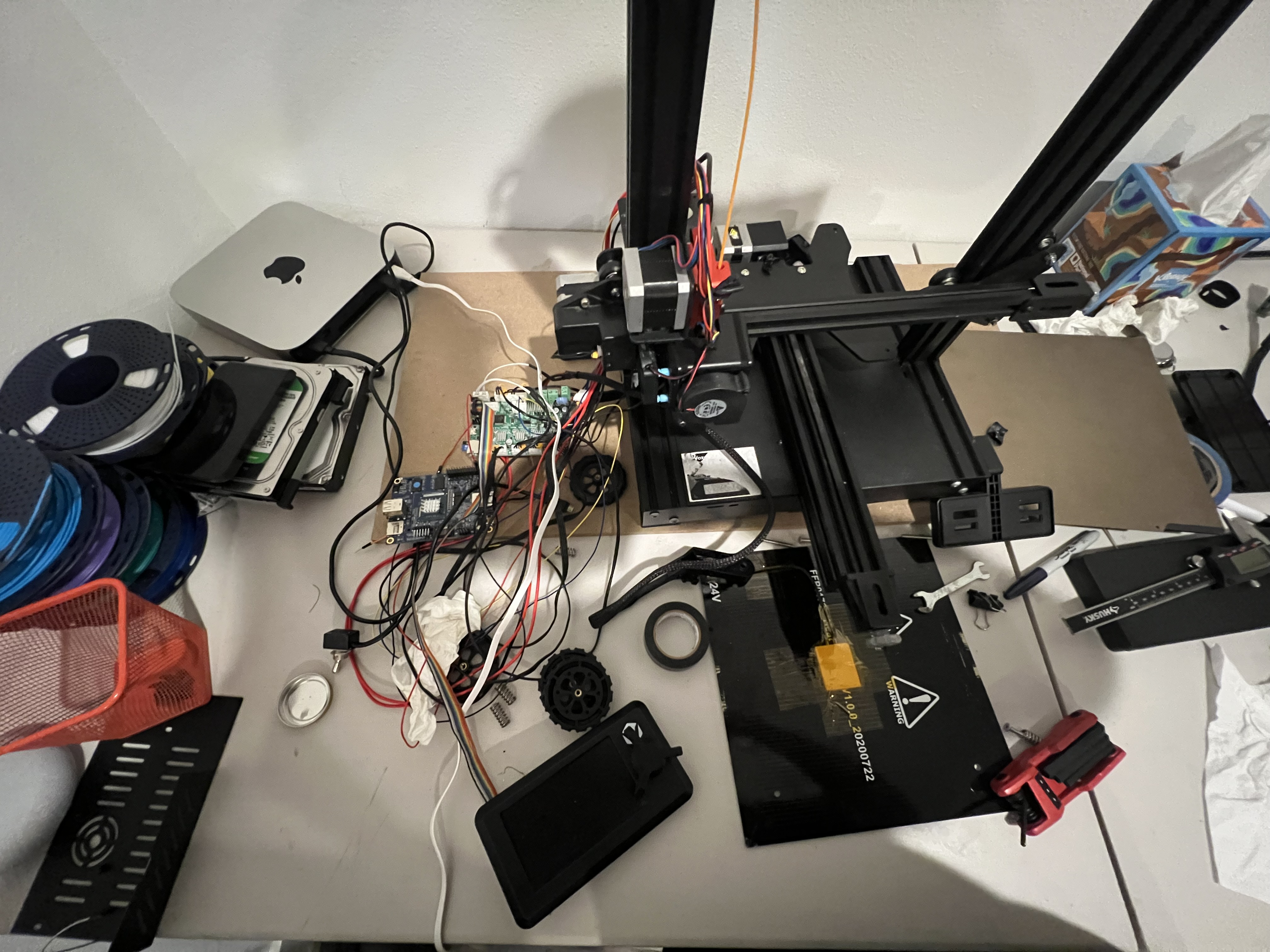
Voxelab Aquila setup with external computational
offload using minnowboard MAX board.
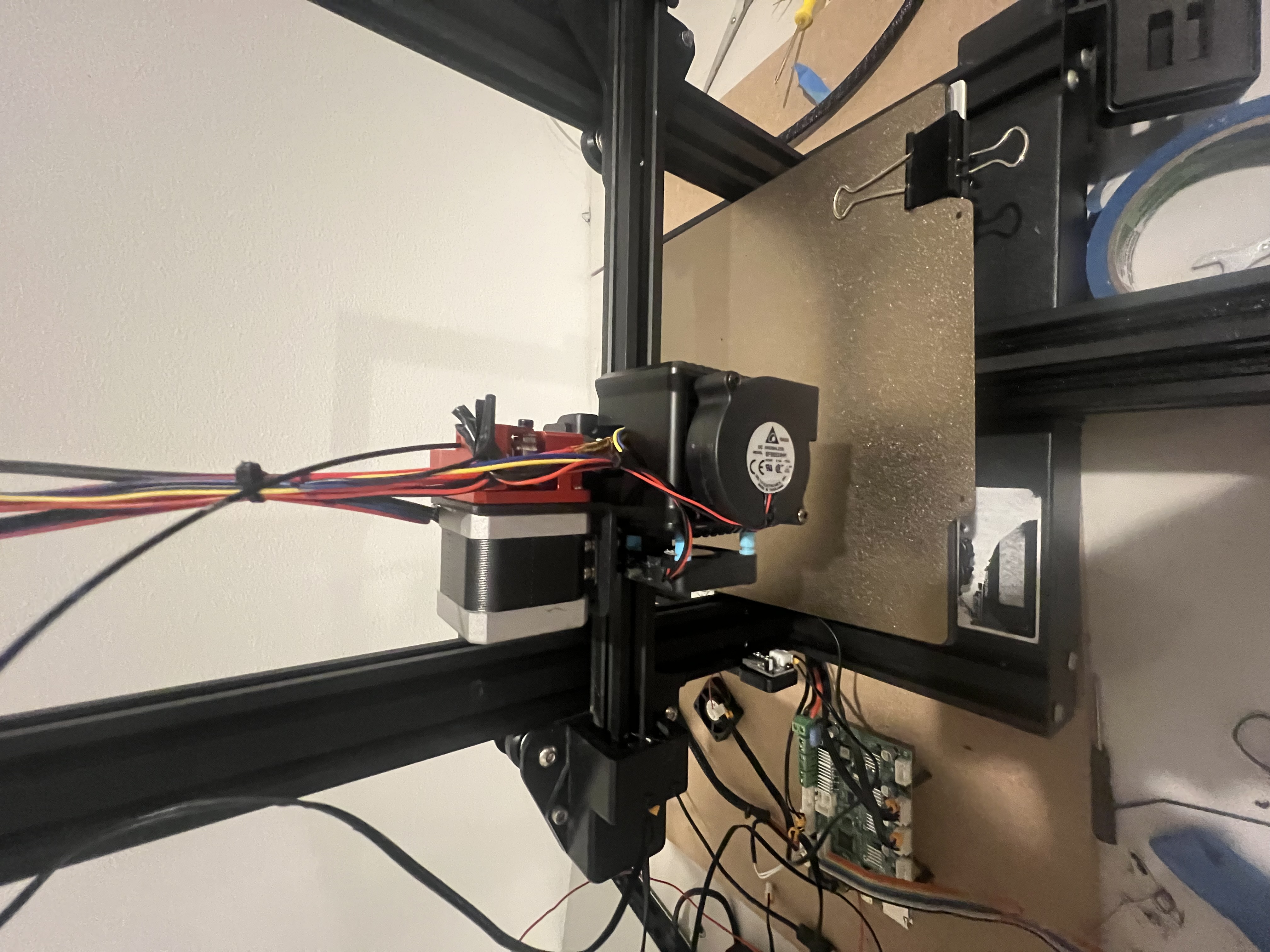
Custom dual-fan cooling configuration for high-speed
printing with intake and exhaust over build plate.
Front fan serves as outtake and fan placed on the
left of the toolhead serves as a intake.
Development Process
Stripped the printer MCU and wired it to communicate
with external computation device (Minnowboard or 5-node
Raspberry Pi cluster)
Modified printer firmware to offload path planning,
acceleration curves, and G-code preprocessing to
external cluster
Performed homing and calibration routines, identifying
communication latency issues between MCU and cluster
Resolved latency by optimizing serial communication
protocol and increasing baud rate from 115200 to 250000
Tested extrusion at higher speeds and encountered
cooling bottleneck where layers weren't solidifying fast
enough
Implemented high-efficiency dual-fan cooling system with
intake and exhaust fans positioned over build plate
Iteratively tuned PID temperature control values to
maintain consistent extrusion at increased feed rates
Technical Details/Decisions
Chose computational offloading over replacing printer
board because it was more cost-effective and allowed
incremental upgrades to computing power
Used Mac Mini to emulate variable numbers of Raspberry
Pis during development to determine optimal cluster
configuration for efficiency and cost
High-efficiency cooling system uses intake fan to pull
ambient air and exhaust fan to remove heat from build
plate area
Cooling configuration critical for maintaining print
quality at 508% speed increase without it layers
delaminated
Serial communication runs at 250000 baud over USB
connection between MCU and cluster master node
G-code preprocessing on cluster includes path
optimization and acceleration planning calculations
5-node RPI setup was most optimal for the voxelab
aquila. It gave the most efficent configuration for the
printer. Not too many, not too few.
The emulated RPI was the PI 4B 4GB using a 500mb capped
wired connection.
Mosquito Guard – Environmental Monitoring System
ESP32 • IoT • Environmental Monitoring • First Place Winner
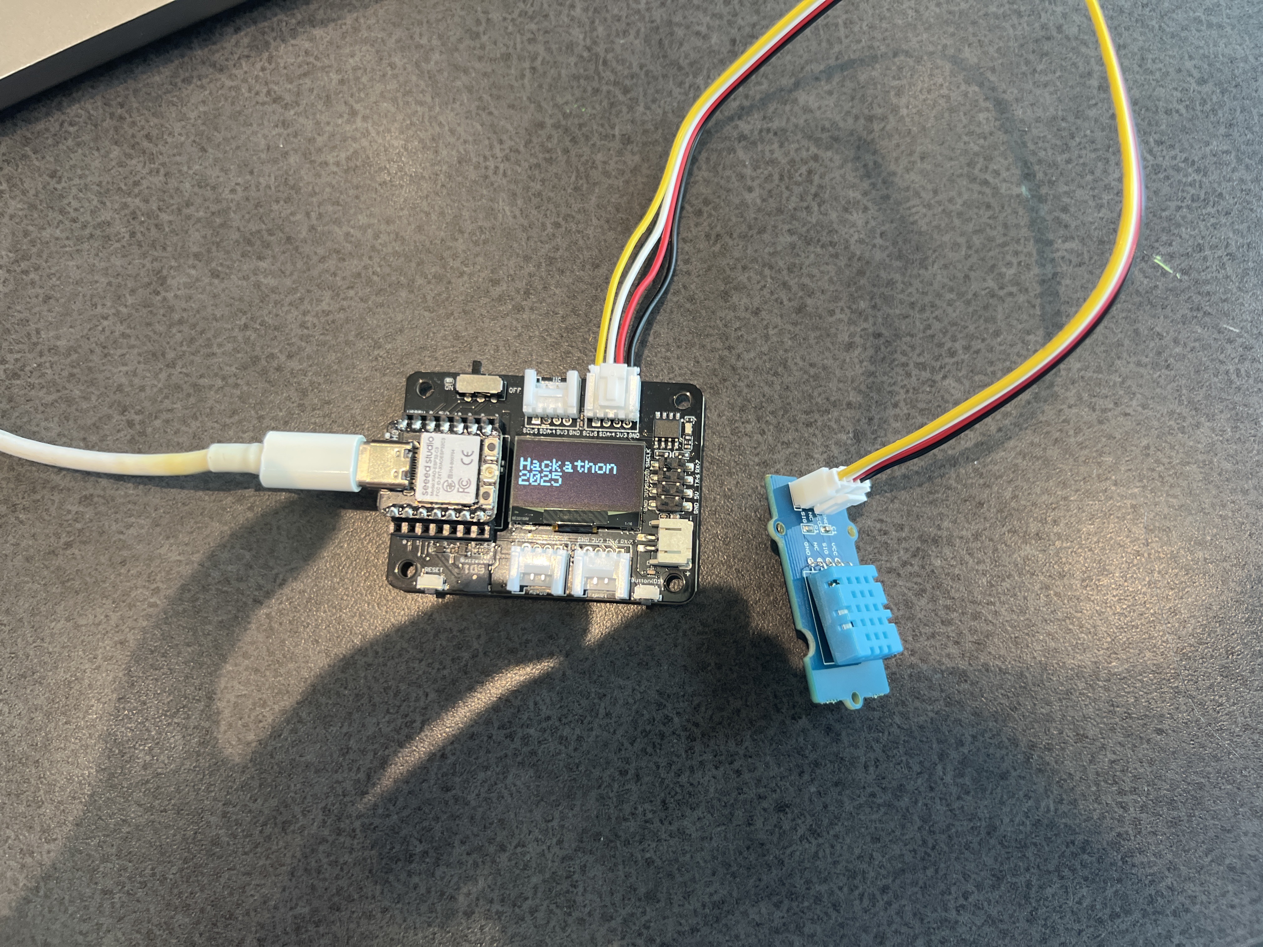
Mosquito Guard is a battery-powered environmental sensor box
that tracks temperature and humidity to calculate real-time
mosquito breeding risk. We built this for under $30 using an
ESP32, DHT11 sensor, and an OLED display all in a 3D-printed
enclosure. The idea was to make something actually
deployable outdoors that could help identify mosquito
hotspots before they become a problem. The system uses a
weighted risk algorithm based on mosquito breeding
thresholds and research, displaying everything through a
standalone WiFi access point with a web dashboard. This
project won first place at the 2025 Chameleon Hackathon.
Real-time mosquito breeding risk calculation based on
temperature and humidity thresholds from research using
set location
Standalone WiFi access point mean no internet required,
you can connect directly to the device to monitor raw
sensor readings
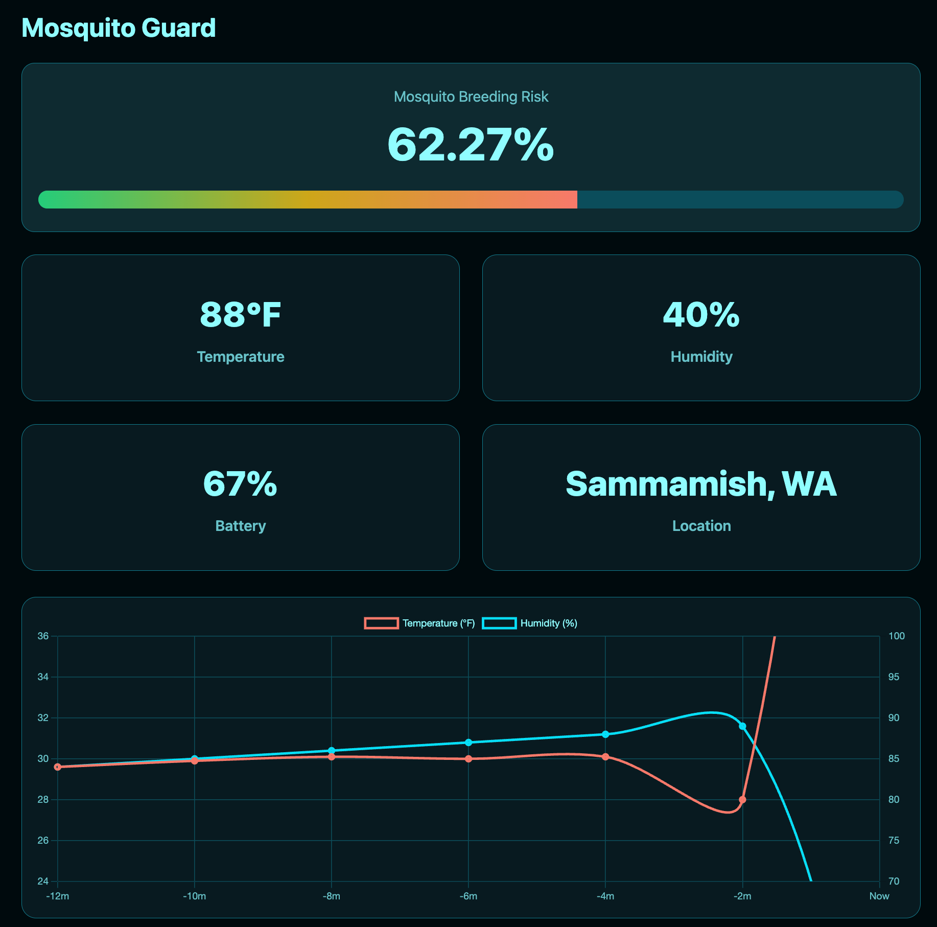
Web dashboard with Chart.js graphs showing historical
trends over selected time periods
OLED display shows connection information and sensor
readings directly on the device
Compact 3D-printed housing designed for outdoor
deployment with room for battery/solar integration
Weighted risk algorithm (60% temperature, 40% humidity)
for accurate breeding condition detection
Color-coded risk meter with gradient display (green to
yellow to red) for instant visual feedback
Features we didnt get time for
Solar panel integration for even longer battery life for
the node.
Additional sensors for more comprehensive data
collection, such as light, air pressure, quality and
moisture of the soil.
Mobile app with notifcations for node status.
Development Timeline
30 minutes in - experimenting with ESP32 and DHT11
sensor, establishing baseline readings
1 hour in - finalized web dashboard design,
implementing data storage and visualization
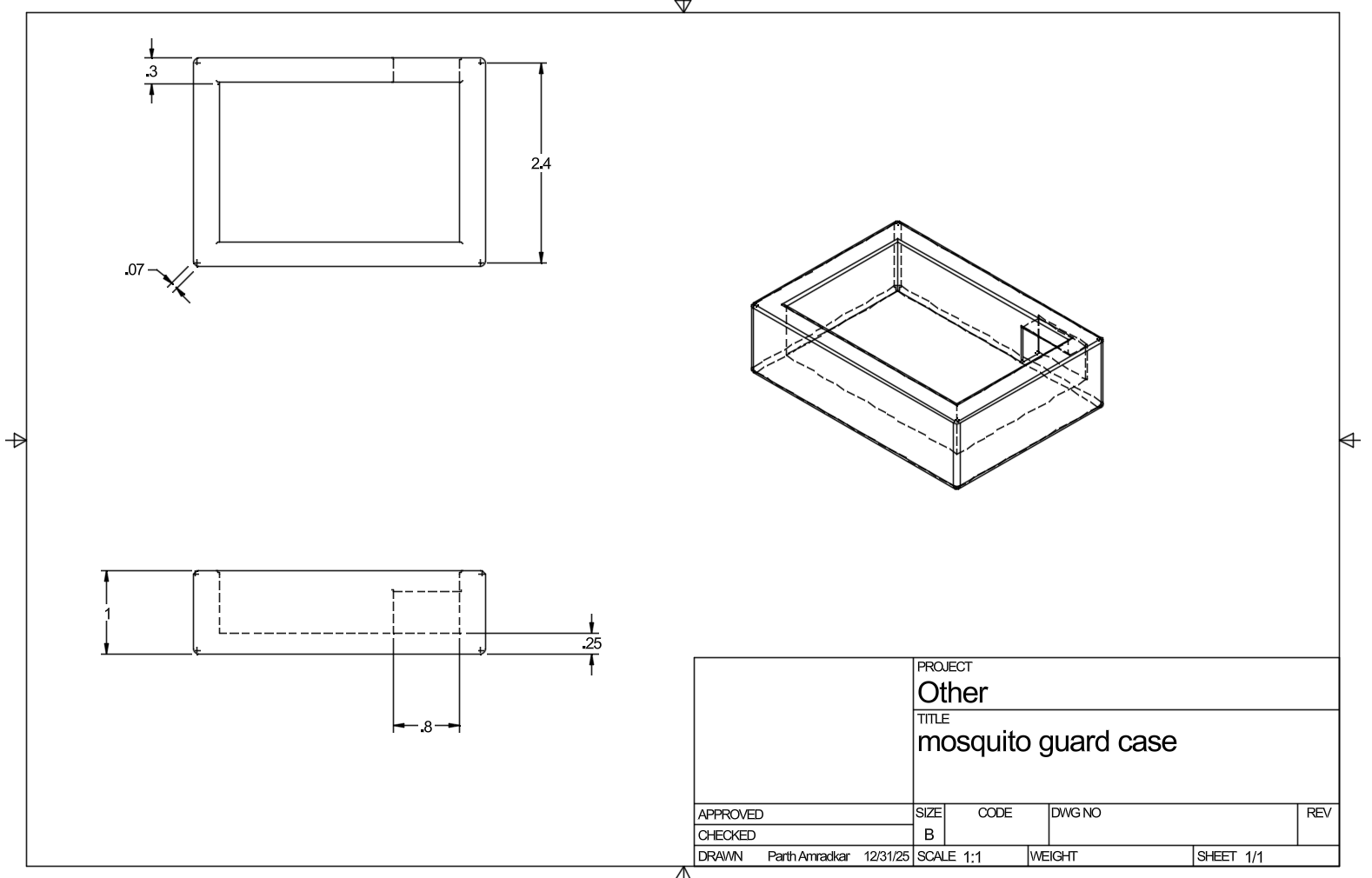
CAD design for hardware enclosure - sent to 3D
printer to print during hackathon
Snip of our presentation we gave during the
hackathon
Development Process
Prototyped on breadboard with ESP32 and DHT11, stored
sensor readings and implemented weighted risk function
Researched mosquito breeding conditions to establish
temperature and humidity thresholds for risk calculation
algorithm
Built web server on ESP32 serving single-page dashboard
with inline CSS/JS to avoid file system bloatware.
Designed risk meter UI with gradient progress bar (green
to yellow to red) updating in real-time based on
weighted score
Integrated Chart.js for dual y-axis graphing of
temperature and humidity trends over chosen time
interval
Modeled and 3D-printed enclosure for the hardware with
wire management and sensor positioning
Wired final assembly inside case with strain relief clip
for DHT sensor cable and configured OLED display to show
WiFi credentials
Tested system outdoors to verify readings matched
expected environmental conditions and risk calculations
Technical Details
Chose DHT11 sensor because it's affordable and accurate
enough for mosquito risk detection DHT22 would be more
precise but overkill for this application. Also it wasnt
provided to us as part of the parts bin.
ESP32 runs in AP mode broadcasting "MosquitoGuard67"
SSID at 192.168.4.1 no router needed just directly
connect to device
Risk calculation uses thresholds where temperature
factor evaluates to 0% at 50°F, 50% at 75°F, 90% at
95°F, then drops above 100°F
Humidity factor calculates to 0% below 30%, 50% at 42%,
and 90% at 80%+ humidity
Final risk score is weighted 60% temperature, 40%
humidity since temperature is the bigger factor in
mosquito lifecycle speed
OLED display (128x64 I2C SSD1306) shows IP address and
connection info so you don't need serial monitor in the
field
Enclosure designed with battery compartment for future
LiPo + solar panel integration for permanent outdoor
deployment
Web server stores last 100 data points in memory for
historical trend visualization without requiring
external database
VEX Stall Detection System
C++ • VEX Robotics • Data Analysis
During the vex season - Pushback, our robot’s intake and
storage system would regularly overheat once it filled up
with blocks. The system used three motors (two 5.5W and one
11W), and when jams happened, they would sit stalled for too
long pulling high current and overheating. This led to
slower performance and risked failures at important times
during matches.
To fix this I created a multi-parameter stall detection
system. It monitors motor RPM, current draw, and temperature
to detect stalls and automatically protect the motors
without taking control away from the driver during scoring.
After testing 12 different stall limits, I landed on a limit
configuration that completely eliminated overheating and
significantly improved reliability throughout the season. My
programming solution was submitted as our teams Innovate
Award entry.
The Problem
Intake system needed to handle large numbers of blocks
without causing heat or performance issues
Motors would overheat when blocks filled the system,
causing excessive current draw
Three motors were affected, two 5.5W motors and one 11W
motor
Overheating reduced intake speed and overall drivetrain
speed during matches
We didnt have time for a intake rebuild so we needed a
programming solution to fufill this.
Needed to protect motors without limiting driver control
during scoring
Research & Solution Development
Explored multiple stall detection methods, including
current-only, temperature cutoffs, RPM detection, and
combined monitoring
Tested each parameter individually to understand how
they behaved under load
Found that relying on a single parameter often gave
unconsistent results
Determined that combining multiple inputs would provide
the most accurate stall detection
Chose to monitor RPM, current draw (mA), and temperature
together
Multi-parameter detection proved far more consistent
than single-threshold approaches
Pics & Demo
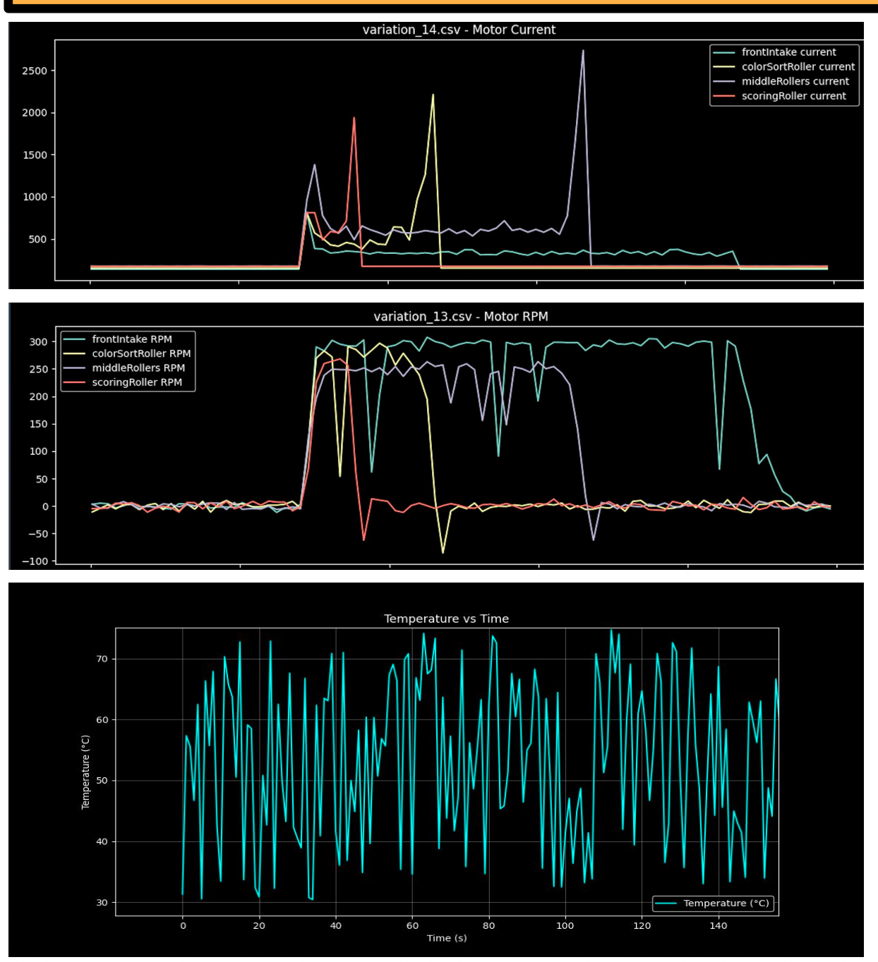
The initial problem we were dealing with was the
clogging of the rollers led to the high temperatures
of the motors which caused a performance
degradation. The neon blue graph at the bottom
displays the average temperature of the motors over
time.
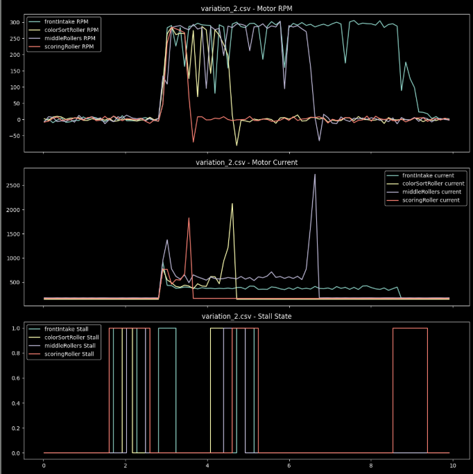
First testing of threshold values - we can see that
the stall detection is very stiff to respond.
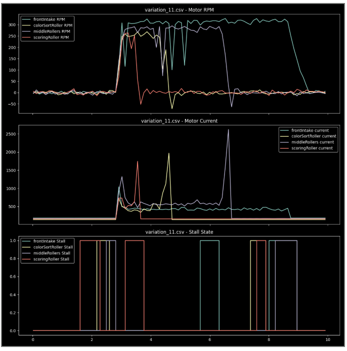
6th variation of threshold values - now we can see
that the stall detection is more responsive to our
monitored values.
Demo of the final programming solution which we used
in tournaments
Implementation Details
Monitoring of RPM, current draw, and temperature delta
RPM stall detection with a recovery window once RPM
rises 20% above the stall threshold
Current monitoring with a <1500mA threshold to catch
electrical stalls early in the intaking process
Temperature delta tracking over 3-second intervals to
detect heat buildup from jams
Automatic power reduction to 20% when a stall is
detected to prevent damage
Driver override option during scoring to allow full
power when needed
Testing Process
Designed a testing process that would stress the system
the most
Tested 12 different configurations to dial in optimal
thresholds
Used generated graphs to analyze current, RPM, and
temperature behavior
Evaluated how often overheating occurred and how it
affected overall bot speed
The 12th configuration proved the most stable and
efficient
Driver could intake blocks without thinking about
stopping intake to allow for maximnum performance
Results & Benefits
Eliminated motor overheating during competition
Reduced unnecessary power draw freeing power for the
drivetrain
Maintained consistent intake performance throughout
entire matches
Improved overall robot reliability and increased
endurance throughout the entire match
Technical Details
Over 25 different thresholds were tested - only 12 made
it to data analysis process
VEX motors suffer much more from heat damage than
regular motors because of their lack of a proper metal
heatsink and the downsides of having a high heat
retention time.
Used matplotlib for data visualization and analysis.
Software development was much better than hardware
changes for us because we then we wouldve had to tune
the new intake as well.
Driver asked for a override and i implemented it in a
trigger hold sequence that completely bypassed the
heating system which then increased the holding time for
the temp deltas and rpm based processes.